Installing the stepper drivers
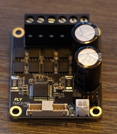
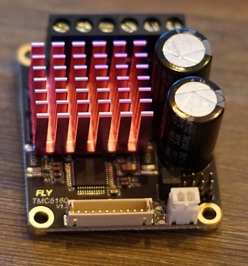
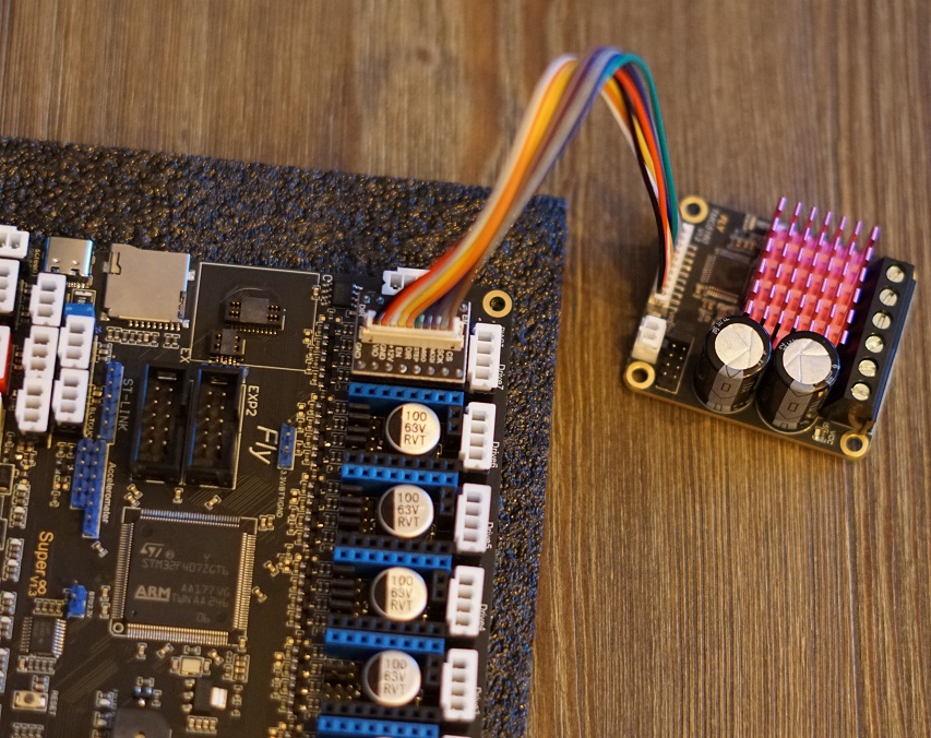
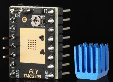
We start off by putting the Heatsinks on the 5160’s. If you don’t do this they will go into overtemp error.
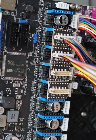
Now we’ll plug in the adapter into the Driver slots. Make sure they are set to SPI like shown in the instructions above here.
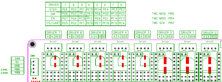
It’s important to use Slot 3-4-5-6 for your AWD system. Slot 7 has some issue’s with SPI. So leave the most Left slot open like shown in the picture below.
Next up is to connect the cable between the adapter board and the External 5160.
Plugging in the 5160’s
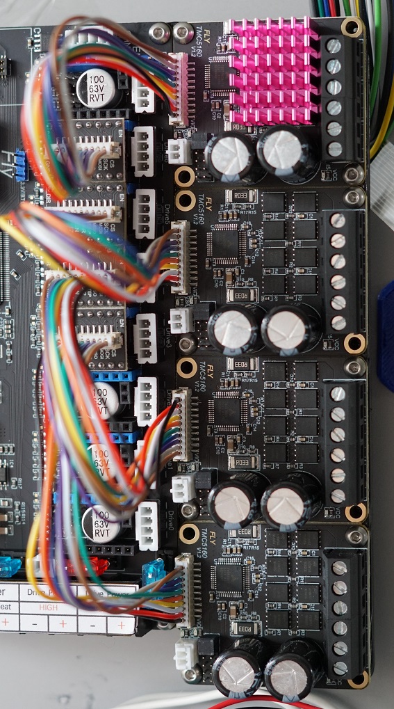
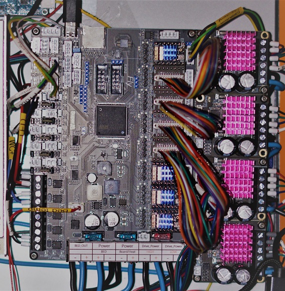
Now it’s time to hookup the 5160’s to the Motherboard.
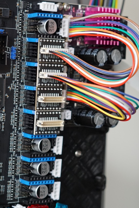
Here you see al the 5160’s installed on the holder and plugged into the Motherboard. Make sure to add all the Heatsinks to the 5160’s. They’ll get overheated fast if you forget these.
Connecting the Motors
First of we’re gonna be putting the TMC2209’s on the Motherboard if you haven’t already done this. Make sure port 0 and 1 are set to UART with the correct jumpers. and plugin the 2209’s. Make sure you plug them in the correct orientation. The part with the pins on the side of the 2209 sits on the outside of the board. and the text on the 2209 is on the inside of the board. like shown Bellow.
First the extruder
For the Plugs coming from the motors we need to make sure we put in the wires correctly into the plug.
The wires have to make a Pair and you can check that with a Multimeter. put it on continuity mode and check wich 2 wires beep when touched. that’s a pair and those get plugged into A A on DRIVER0 the other 2 wires are automaticaly also a pair and get plugged into B B.
Repeat this for your Z motor on DRIVER1
5160 motor setup
Next up we’re going to be wiring up the motors to the 5160’s.
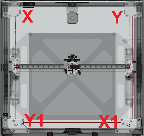
First of we’re going to be wiring the X motor into the 5160’s that’s plugged into DRIVER6. This should be your top 5160.
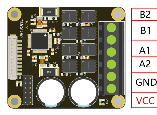
Again measure the continuity of the motors and put your first pair in B2 and B1 and put the other pair in A1 and A2.
Repeat this for the X1 in slot DRIVER5,Y in slot DRIVER4,Y1 in slot DRIVER3.